samedi 24 novembre 2012


Design Charette from SketchUp Basecamp
A couple of weeks ago I went to Boulder to attend the 4th SketchUp Basecamp.
SketchUp has hosted this gathering every couple of years, to get users
and programmers together to discuss what's planned, what should be
planned, what people want to see, and to see examples of how some
SketchUp experts are using the software. There are always a bunch of us
third-party product people running around as well, including writers
like myself, trainers, rendering engine companies, dynamic component
producers, and the like.
I plan to write up my impressions of the entire three days, but first I wanted to post about the design charette - the main activity on the third and final day (which ended around lunchtime).
"Charette" is a term I hadn't heard as an engineering student. It is generally used in architecture, when a group of students or designers need to come up with a problem-solving design in a short time. The Basecamp charette participants were told to form groups of about 10, and the assignment was to either design the classroom of the future, or some sort of organizational system for storing educational technology (tablets, printers, etc).
I ended up not participating myself (got involved in a couple of meetings instead), and I wasn't there when the results were presented (lunch meeting!). So I don't know how many groups opted for the organizer and how many did the classroom. But I do know who won, because I know most of the members of that group!
So imagine that you and some colleagues have TWO AND A HALF HOURS to come up with a design and get it into some sort of presentational format. Rather high pressure! But these are SketchUp experts, who are also fluent in LayOut, so great things were happening.
My friend Eric Schimelpfenig was on the winning team, and he sent me the winning model as well as the LayOut (presentation) file. Here are some shots of their design. For each image, click to view the entire thing - you might not get the full image in the blog format.
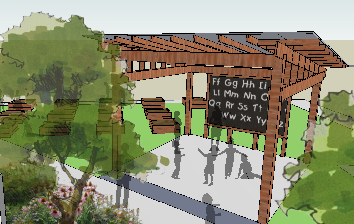
The overall view shows one enclosed classroom, surrounded by lots of landscaped outdoor space. (I assume this is located somewhere NOT being pounded by Hurricane Sandy, as we are right now...)
I plan to write up my impressions of the entire three days, but first I wanted to post about the design charette - the main activity on the third and final day (which ended around lunchtime).
"Charette" is a term I hadn't heard as an engineering student. It is generally used in architecture, when a group of students or designers need to come up with a problem-solving design in a short time. The Basecamp charette participants were told to form groups of about 10, and the assignment was to either design the classroom of the future, or some sort of organizational system for storing educational technology (tablets, printers, etc).
I ended up not participating myself (got involved in a couple of meetings instead), and I wasn't there when the results were presented (lunch meeting!). So I don't know how many groups opted for the organizer and how many did the classroom. But I do know who won, because I know most of the members of that group!
So imagine that you and some colleagues have TWO AND A HALF HOURS to come up with a design and get it into some sort of presentational format. Rather high pressure! But these are SketchUp experts, who are also fluent in LayOut, so great things were happening.
My friend Eric Schimelpfenig was on the winning team, and he sent me the winning model as well as the LayOut (presentation) file. Here are some shots of their design. For each image, click to view the entire thing - you might not get the full image in the blog format.
The overall view shows one enclosed classroom, surrounded by lots of landscaped outdoor space. (I assume this is located somewhere NOT being pounded by Hurricane Sandy, as we are right now...)

This view of the classroom, minus roof, shows the main room with circular desks and a loft area with beanbag (!) chairs.

There aren't many (if any?) doors that close. A nice flower garden with paving stones is just off (and visible from) the main classroom.

Behind the classroom is an area with interactive signage.

Here's the greenhouse with solar roof:

And this is the open-air Council House.
Next to the Council House are some CSA-style vegetable plots, and the overlook features a human sundial.

Heading back into the main classroom area, there are some flat screens where the kids can see and chat wtih their fellow students across the world.

Have you noticed the translucent people? You can find them by searching
for "silhouette" in the 3D Warehouse. These are components that always
face the right way, and their black color was made translucent - an easy
way to get a quick and dirty rendering without using any other
programs.

Various views of this design, along with larger detailed views, were
assembled into a LayOut document, which was then presented to the
charette judges.
Congrats to the winning team! I'm not sure if the they had a team name, but here are the participants:
Zack Mertz
Rashad Al-Ahmadi
Mike Tadros
David Pillsbury
Jeffrey Orkin
Wyatt Thompson
Bertier Luyt
Yael Kadem
Eric Schimelfpenig
John Pacyga
Improve usage of BIM during early design phases
When I was collecting ideas for a book chapter on BIM (that seemed to
never have emerged after that), I collected 10 ideas, which I believe
still reflect good recommendations to improve the usage of BIM during
the early design phases. These ideas are related to BIM software, but
you can apply them in any flavor, as long as you can model with Building
Elements, Spaces and have control over representation.
Introduction
This article gives an overview of several recommendations and tips, to
better apply BIM applications and BIM methodologies, in the context of
the early design phases. Many of these tips are applicable in any BIM
application and they are based on experience gathered from teaching,
researching and using BIM software.
Sometimes they could help software developers to improve the workflow of their particular BIM implementation.
Sometimes they could help software developers to improve the workflow of their particular BIM implementation.
Tip 1 : Gradually increase the amount of information
In the early design phases, the architect makes assumptions and lays out
the main design intent. There are several different aspects which can
assist this process to cope with a gradual increase of detail and
information.
Scale-Sensitive objects allow the design to properly reflect the scale of focus
The display of a window on a scale 1:100 is necessarily simplified,
while the same object, with the same parameters on a scale 1:20 should
display more detail, especially with regard to the connection of the
frame to its enclosing wall. Most current BIM systems allow this to
occur automatically, but when extending the library of “objects” or
“families” or “symbols”, it is important to take this into account.
Start with generic elements
Walls, floors and roofs can typically be composited from several layers
of applied materials, but in the early design phases, this can
wrongfully suggest that the design information is more elaborate than it
actually is. It is more important to indicate a wall to be an exterior,
load-bearing wall and maybe distinguish between a select few project
variations, rather than on very specific compositions.
While not readily available in common software implementations, it is possible to automate the replacement of generic or default elements with specific and more detailed compositions, e.g. through scripting. But currently, this has to be done by either modifying the generic structure or by manually assigning a more specific composition.
While not readily available in common software implementations, it is possible to automate the replacement of generic or default elements with specific and more detailed compositions, e.g. through scripting. But currently, this has to be done by either modifying the generic structure or by manually assigning a more specific composition.
Tip 2 : Make Mass Models and Volume Studies
Most BIM tools support the Masterplan Scale Level with Mass Modeling
tools. And in some cases, there are even automated routines to generate
regular building elements from these mass models.
Unfortunately, this is commonly implemented as a one-way process. It would be good that BIM developers realize that allowing the user to freely migrate between Scale Levels and Design Phases can better support the design process. (FWIW, this was the main topic of my PhD in 2007)
To some extent, the applications even support this, but not as fully as possible. E.g. we noticed when using this in AutoCAD Architecture, that once you generate the walls and floors from the Mass model, that there was no way back. Modifying the Mass model did not properly reflect on the generated elements.
Tip 3 : Model with Spaces/Rooms
Closely related to Mass models are Spaces or Rooms. While most BIM
software supports the notion of a Room or Space or Zone object, it is
sometimes closer to annotation than to modeling. In e.g. Revit, you can
only insert Rooms when the enclosing walls, floors and roofs have been
modeled. And while you can model with standalone Zones in ArchiCAD, they
only present all their features when the enclosing elements are
available and used for Zone generation. This is remarkable, from the
point-of-view of the designer, as the room or space is probably one of
the most fundamental design entities, directly reflecting how the model
proposes a solution for the design program or brief. However, even then
it is of utmost importance to use the Room/Zone/Space features to
indicate functions and generate listings early on, which can be
performed without much effort. Such listing are invaluable for quick
program assessment and project cost estimation. And they do form the
basis for energy analysis too.
A good example of this was our usage of building function analysis we performed for a recent study of elderly care centers. Based on 2D PDF and CAD drawings, used as an underlay, we traced the different floor plans using the Zone tool in ArchiCAD, with a custom set of categories. While we attempted to be precise, initially, time constraints enforced a more sloppy and fast approach at peak time for some later cases. However, it did allow us to have a spatial overview of the projects, distinguishing between e.g. circulation, technical rooms, leisure and sanitary rooms, as well as administrative spaces, to be compared between the case studies. In addition, we could present a 3D spatial model, with automatically generated listings alongside. It provided more flexibility, although most of the analysis was still carried out in a spreadsheet.
A good example of this was our usage of building function analysis we performed for a recent study of elderly care centers. Based on 2D PDF and CAD drawings, used as an underlay, we traced the different floor plans using the Zone tool in ArchiCAD, with a custom set of categories. While we attempted to be precise, initially, time constraints enforced a more sloppy and fast approach at peak time for some later cases. However, it did allow us to have a spatial overview of the projects, distinguishing between e.g. circulation, technical rooms, leisure and sanitary rooms, as well as administrative spaces, to be compared between the case studies. In addition, we could present a 3D spatial model, with automatically generated listings alongside. It provided more flexibility, although most of the analysis was still carried out in a spreadsheet.

A concern we still has was deciding between modeling the net spaces in between the walls or the gross area and volume, up to the outer extents of the facade. Ideally, you'd have both, but you might not want to model both.
Tip 4 : Don’t import SketchUp models into BIM software
While most current BIM software supports the import of SKP models and
even interprets the faces as actual walls, floors and roofs, it is
better not to rely on this functionality. In most cases, the SketchUp
model is good “as is”, but not “well-formed”. It is not built up to the
accuracy or the structure expected for a correct and manageable BIM
model.
However, if you do insist, don't bother modeling the thickness of walls and roofs in SketchUp. Use it for where it shines most: exterior volume studies. It is however possible to load this model as a reference object, to assist proper remodeling with actual BIM tools, similar as using 2D drawings as underlays.
However, if you do insist, don't bother modeling the thickness of walls and roofs in SketchUp. Use it for where it shines most: exterior volume studies. It is however possible to load this model as a reference object, to assist proper remodeling with actual BIM tools, similar as using 2D drawings as underlays.
Tip 5 : Design on grid and on axis
In most cases, to have flexible and sound models, it makes sense to
ensure that walls, columns and beamse are properly aligned on grids and
placed on axis. While not all BIM applications use Grids as actual
design entities, those that do allow the user to more properly embed
design intent in the model and have clearer indications of connectivity,
adjacency and general topology in the building. A good design grid
setup will allow faster modeling and allow for a faster design workflow.
Tip 6 : Model as little as possible...
While BIM software presents an enormous array of tools and functions, it is wise to adhere to an approach of least effort.
Model as little as possible, with as few elements as possible in as few files as possible.
For construction documents and for technical details, it is good to have
detail and larger project can benefit of division into several files,
but in the early design phase, it is better to try to be efficient.
- Strive to use the minimal amount of entities and control them with as few parameters as possible.
- Don’t split elements (e.g. use a full floor and wall and ignore the interconnections at this stage).
- Adapting the model to design changes is much more flexible and efficient with a smaller set of objects to master.
Tip 7 : Represent for concept
While it is tempting to embed photorealism in the design process, it is
only a by-product and can often lead to false assumptions. It is
advisable to limit some aspects of representation, ensuring that all
visual output clearly reflects the immaturity of the design.
- Ignore texturing or fall back on simplified materials;
- Avoid hatching, especially when the scale would not present this properly;
- Limit the amount of annotation to basic room tags and some major dimensions (e.g. height levels);
- Use conceptual colors, clearly indicating function and design intent, rather than materiality;
- Make all cut elements pure black; don't show wall, slab and roof layers at this stage.
Tip 8 : Use simple templates
A good template is the key to productivity. However, it would be naive
to assume that a single template should cater for all phases in the
design process. It would be good to have a very basic design template,
small and without clutter, with a subset of functions and materials.
Postpone the use of extensive templates to the later phases in the design process. If the user needs to scroll to get through the list of materials, line types, layers, compositions or other settings, then the template is too extensive. Less is more indeed.
Postpone the use of extensive templates to the later phases in the design process. If the user needs to scroll to get through the list of materials, line types, layers, compositions or other settings, then the template is too extensive. Less is more indeed.
Tip 9 : Use external references and images
BIM models are often the collection of information from different
sources, such as site measurements, images, reference documentation.
While all these documents belong in the design, they should be kept
outside of the model. If supported by the software, use underlays,
external maps and pictures.
Do not "import" CAD drawings, especially when they can generated additional clutter, such as layers, line types or annotation styles. (However, if your software supports underlays/XRefs, then you can attach the CAD drawing and yet retain your own BIM template structure).
Do not "import" CAD drawings, especially when they can generated additional clutter, such as layers, line types or annotation styles. (However, if your software supports underlays/XRefs, then you can attach the CAD drawing and yet retain your own BIM template structure).
Tip 10 : Use the right tool for the right job, but keep only one master
A hybrid usage of applications is quite common. The design can be
elaborated in modeling, drafting and BIM software and at the same time
in visualization and simulation tools. However, to ensure consistency,
maintain a single master model; which is, preferably, the BIM model.
If necessary, host other parts of the design in the main BIM model, e.g. by inserting or referencing external geometry and keep the original for all design changes. 2D information can also be hosted, as flat drawings or as PDF documents.
If necessary, host other parts of the design in the main BIM model, e.g. by inserting or referencing external geometry and keep the original for all design changes. 2D information can also be hosted, as flat drawings or as PDF documents.
If at all possible, automate the updating of changes or the workflow.
This is actually very similar to game development, where “assets”
(geometry, textures, sounds, animations) can be created in several
applications, yet a full pipeline is established to ensure that
different people all work on the same project. Updates to these assets
are reflected in the authoring environment.
A good example can be experienced in a visualization process. E.g. you can "link" an ArchiCAD model to Cinema4D for rendering and animation and even link this model to Unity3D, for realtime exploration. Updates to the BIM model reflect in the visualization model and consecutively reflect in the realtime model. The exact same workflow is also supported between Revit, 3ds Max and Unity.
Another motivation to keep using the BIM model as the master geometry for visualization are the flexible representations. In a pure modeling software, your geometry is "as is" (unless you apply a fully parametric process). But in BIM, this geometry can be regenerated based on different criteria: e.g. layer settings, scale level, building phase, level of detail (e.g. load-bearing only; finishes) and also cutout sections. And you don't have to export the whole model as one single file. When you create complementary views in the BIM software, you can export the model in chunks and then assemble them in the visualization software.
Conclusion
While all of these 10 “rules” can only be taken as recommendations and
can be disregarded at times, it is our belief that they can assist with a
proper application of BIM in the early stages of the design process.
These suggestions have been motivated to counter some skepticism
regarding BIM, as many people are convinced that BIM should only be
utilized when the design is crystallized. This would be unfortunate, as
the main advantage of using BIM is the possibility to better inform the
designer about the project and its performance (e.g. cost, energy,
esthetics) and improving or adapting the project should be done
preferably during the early design phases, when this kind of
modifications is still possible.
The next mind map is a more graphical summary of the 10 tips/recommendations...
The next mind map is a more graphical summary of the 10 tips/recommendations...

Moment of Inspiration > Mac version available for beta testing
MoI (Moment of Inspiration) has been around for quite some
time, as a standalone modeler for Windows. It is developed by the
former creator of Rhinoceros 3D and focuses on freeform geometry
primarily. The phrase "SketchUp for MCAD" is sometimes heard to describe
this software.
This is a NURBS modeling application, with a particular attention to user interaction and a minimal interface. You can use it mostly using a mouse or even a pen (e.g. from Wacom) and I assume that it would work mostly fine even on a touch screen. Could the OSX version be a hint of a possible future iOS version for iPad? I don't know, but it makes sense and would be really welcomed.
The interface is mostly icon-based and is not crowded at all (unlike many other CAD applications). The tools are easy to understand (especially when you have been using a program like Rhino before) and there are no commands to type or menu's to step through. There are shortcuts you can use, however, to get more productive.
Modeling is fairly interactive and everything can be seen fully shaded in the viewports. When you activate a tool, sometimes more tools are visible in an opening sub-panel and the options for the particular tool are displayed above the tools in an additional part of the side pane.
 |
| MoI in action (with some annotations by me) |
All the usual basic commands are available, from extrusions and lofts,
to sweeps, revolves, a set of primitive solid objects and Boolean
operations. There is also a set of Curve creation tools and especially
the sketching of a curve makes sense in this application.
But it is also a real CAD application, so you can edit curves with their control points, use snapping and coordinates and import/export to other software.
It's native file format is the same as in Rhino: OpenNURBS (*.3dm), but it can export to IGES, sat, STEP, obj, stl, 3ds, lwo, fbx, SketchUp and even AI (Illustrator) using a projected view. You can read some other formats too: OpenNURBS, IGES, SAT and STEP and Illustrator files (ai, eps or PDF format). So you can easily integrate this application with other software.
It is a commercial, closed-source application and the Windows version was about $295, so I expect the OSX version to have the same price, when it is officially released. You can test the beta-version for free and there is a trial for the Windows version available.
Info on http://moi3d.com/osxbeta.htm

Open IFC Tools : Open Source IFC Libraries and software
Open IFC Tools (http://www.openifctools.org)
This is a set of Open Source (for non-commercial use) libraries written in Java. It should work on Windows, Linux and OSX.
They follow a modular approach, where different packages are being released in order:
This is a set of Open Source (for non-commercial use) libraries written in Java. It should work on Windows, Linux and OSX.
They follow a modular approach, where different packages are being released in order:
- Open IFC Java Toolbox
- Boolean Modeller
- IFC-loader for Java3D
- 4D Scheduling Assistant
Currently, only the Toolbox is available, together with a Java
Webstart demonstration to launch the software directly from a browser.
This automatically installs the necessary extensions for Java3D, OpenGL,
GlueGen.
I tried the web-demo but first had to update Java3D on my Mac (as mentioned on http://www.openifctools.org/Open_IFC_Tools/mac_java3d.html).

This viewer loaded the ArchiCAD file without problems and
displayed it adequately. You get a view on the actual IFC code, a 3D
visualization, the hierarchic object tree of the Spatial structure and
the particular attributes of selected entities, which is exactly what
you need from a viewer.
The yellow color is the highlight color of the wall I
selected, on the ground floor ("Gelijkvloers" in Dutch). It displays the
wall information, the ID (unique), the Name (as named inside ArchiCAD)
and the connectivity with other objects.
This is quite comparable to what is provided by Solibri Viewer, so the implementation is fairly complete.
For an end user, you might be a bit scared away with all the
nitty-details from the IFC files and indeed, a literal display of what
is inside an IFC file can be pretty daunting, when you are accustomed to
a more user-friendly display from e.g. ArchiCAD or Revit.
2012 will be more mobile and synced
This is a short post talking about mobile CAD. Posted from my new phone.
This year I want to take a look at BIM, model viewing and sharing on mobile devices, hopefully on different platforms. So far I'm impressed by BIMx and Magicplan, but there is much more.
This year I want to take a look at BIM, model viewing and sharing on mobile devices, hopefully on different platforms. So far I'm impressed by BIMx and Magicplan, but there is much more.

Inscription à :
Articles (Atom)